
Hall sensor with ESP32 | RM0435 Sensor with esp32
- Pawan Meena

- Feb 15
- 2 min read
Interfacing RM0435 Hall Sensor with ESP32
Introduction
The RM0435 Hall Sensor is a magnetic field sensor that can detect the presence of a magnetic field and output a digital signal. In this tutorial, we will learn how to interface the RM0435 Hall Sensor with the ESP32 microcontroller to read the sensor's output.
Components Required
ESP32 Development Board
RM0435 Hall Sensor
Breadboard and Jumper Wires
USB Cable for Programming the ESP32
Arduino IDE Installed on Your Computer
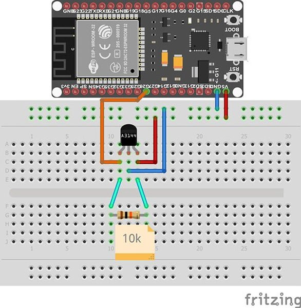
Wiring Diagram
Connect the RM0435 Hall Sensor to the ESP32 as follows:
RM0435 VCC pin to ESP32 3.3V pin
RM0435 GND pin to ESP32 GND pin
RM0435 OUT pin to ESP32 GPIO pin (e.g., GPIO 23)
Arduino IDE Setup
Open the Arduino IDE.
Go to File > Preferences.
Add the following URL to the Additional Board Manager URLs field: https://dl.espressif.com/dl/package_esp32_index.json
Go to Tools > Board > Boards Manager.
Search for "ESP32" and install the package.
Code Example
Use the following code to read the output from the 4 RM0435 Hall Sensor:
   // Include necessary libraries
#include <Arduino.h>

// Define GPIO pins for Hall sensors
#define HALL_SENSOR_1 26
#define HALL_SENSOR_2 27
#define HALL_SENSOR_3 12
#define HALL_SENSOR_4 14

void setup() {
  // Initialize serial communication
  Serial.begin(115200);

  // Set up Hall sensor pins as input
  pinMode(HALL_SENSOR_1, INPUT);
  pinMode(HALL_SENSOR_2, INPUT);
  pinMode(HALL_SENSOR_3, INPUT);
  pinMode(HALL_SENSOR_4, INPUT);

  // Print setup message
  Serial.println("Hall sensor test initialized. Monitoring analog sensor values...");
}

void loop() {
  // Read the analog value of each Hall sensor
  int sensor1Value = analogRead(HALL_SENSOR_1);
  int sensor2Value = analogRead(HALL_SENSOR_2);
  int sensor3Value = analogRead(HALL_SENSOR_3);
  int sensor4Value = analogRead(HALL_SENSOR_4);

  // Print the value of each sensor to the serial monitor
  Serial.print("Sensor 1: ");
  Serial.print(sensor1Value);
  Serial.print(" | Sensor 2: ");
  Serial.print(sensor2Value);
  Serial.print(" | Sensor 3: ");
  Serial.print(sensor3Value);
  Serial.print(" | Sensor 4: ");
  Serial.println(sensor4Value);

  // Delay to avoid spamming the serial monitor
  delay(100);
}
Uploading the Code
Select the correct board and port in the Arduino IDE:
Go to Tools > Board and select "ESP32 Dev Module".
Go to Tools > Port and select the appropriate COM port.
Click on the upload button (right arrow icon) to upload the code to the ESP32.
Testing the Sensor
Open the Serial Monitor in the Arduino IDE (Ctrl + Shift + M) to view the output. Bring a magnet close to the Hall Sensor and observe the messages:
If you see "Magnetic field detected!", the sensor is working correctly.
If you see "No magnetic field.", the sensor is not detecting any magnetic field.
Troubleshooting
Ensure that the wiring is correct and secure.
Check that the ESP32 board is properly selected in the Arduino IDE.
Make sure the RM0435 Hall Sensor is functional.
Conclusion
In this tutorial, we successfully interfaced the RM0435 Hall Sensor with the ESP32 microcontroller. You can now use this setup for various applications, such as detecting the presence of magnets or creating simple proximity sensors.
Comments